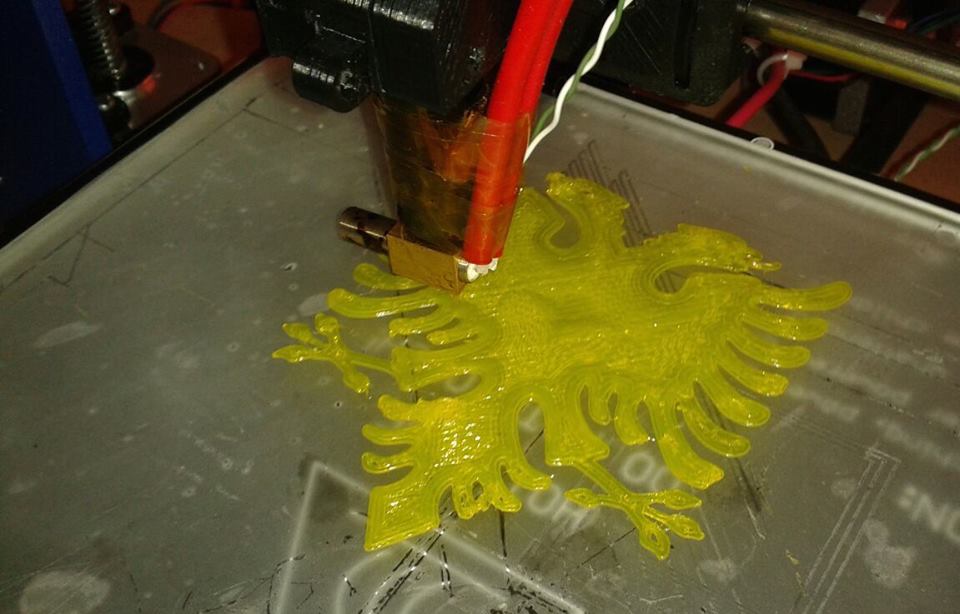
According to Wikipedia, 3D printing is any of various processes used to make a three-dimensional object. I would define a 3D printer as “a computer-controlled machine that lies layers of material on top of the other layers, in order to create an object defined by a 3D model”. 3D printers are used in industry (as they are a kind of industrial robot), for rapid prototyping, distributed manufacturing and as well as food industry, biotechnology, etc.
The principle of work
Basically a 3D printer creates layers on top of each other, based on an electronic 3D model. There are different ways to achieve this, or different techniques of 3D printing.
The easiest to understand is called Fused Deposition Modeling (FDM). A filament (thermoplastic, metal, etc.) passes through an extrusion nozzle (A.K.A. extruder), a device which can turn on and off the flow of the filament. This nozzle is heated in order to melt the filament. This kind of printer has steppers (usually 3 or 4) which make the X, Y and Z movements possible. These steppers move the nozzle in a 2D plane, allowing it to deposit the melted filament. After the first layer is printed, the Z stepper(s) would move the nozzle in order to deposit another layer on top of the first one. This process goes on until the 3D model is fully printed.
Another way of 3D printing is called Stereolithography (SLA). This technique uses a liquid photopolymer (resin - the material) and a ultraviolet (UV) laser to build the layers. For each layer, the UV laser passes through a cross section of the resin liquid. When this liquid comes in contact with the UV light from the laser, it solidifies and the solid layer joins to the other layers.
Selective Laser Sintering (SLS) is another 3D printing technology, which uses a powerful laser to fuse small particles of powdered material together in an object that has the desired (designed) shape. The laser selectively fuses the powdered material by scanning the cross-sections (or layers) generated by the 3D modeling program on the surface of a powder bed. After each cross-section is scanned, the powder bed is lowered by one layer thickness. Then a new layer of material is applied on top and the process is repeated until the object is completed.
All the 3D printers which use one of the above methods need the help of a computer in order to analyze the 3D model and turn it into the needed instructions for the 3D printer. This means that 3D printers are numerically controlled machines.
Building a 3D printer
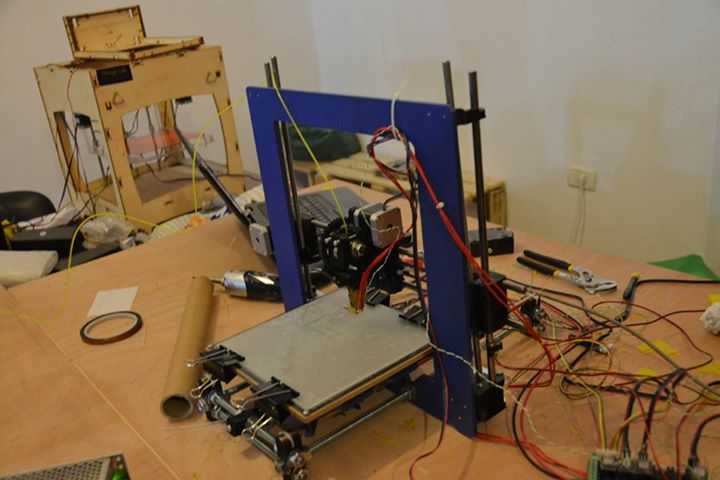
So we started early this year, getting all the components needed for a Prusa i3 and putting them into one piece. If you are thinking of getting a 3D printer kit and build it by yourself, check out RepRap and/or RepRapWorld. They have plenty of information about 3D printers in general and also a great catalog of items you can buy to build up your own 3D printer.
You can see another 3D printer in the background, but we are changing that into something equally awesome.
Assembling the items is different for different printers, so I don’t have much to say about it. But one thing is sure, you can get rid of every issue during this step with a single phrase in mind: RTFM (Read The Freaking Manual). RepRap has a long list of machines and manuals to build all of them, so what you have to do is nothing more than reading the manual and act upon it. If you don’t, you will have problems just like us. One of them that can be mentioned is the fact that the gears were eating up on the filament while printing, which then would stuck there, curl up and block the nozzle, ergo stopping the printing process.
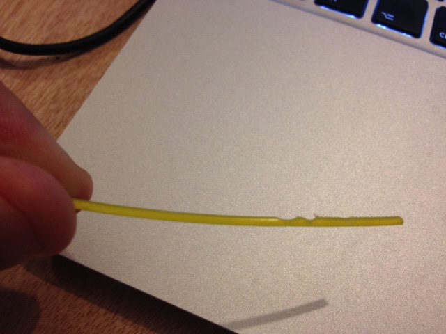
We somehow managed to fix this issue, and the hungry gears were part of history. There were also other issues; we successfully blocked one extruder, so we had to change that one. But in general, we managed to fix almost all the mechanical issues that we had and the building process finished nice.
Software to use
As a 3D printer is a computer-controlled machine, it surely needs (at least) a software to control it. Actually, for the whole 3D printing process you need two software: one for the preparation of the layers and another one for actually telling the printer how to print these layers. I’m excluding the 3D modeling software here, because assuming you have a 3D printer doesn’t implies that you also make the 3D designs. You can model everything by yourself, you can ask someone else, or you can download them and print them.
The software that prepares the layers from a given 3D model is called “a slicer”. Think of a slicer as a black box (you don’t need to know how it works inside) where a 3D model goes in and G-code goes out. There are a lot of slicers, but Slic3r was our choice. It is free, open source and works fast with many printers.
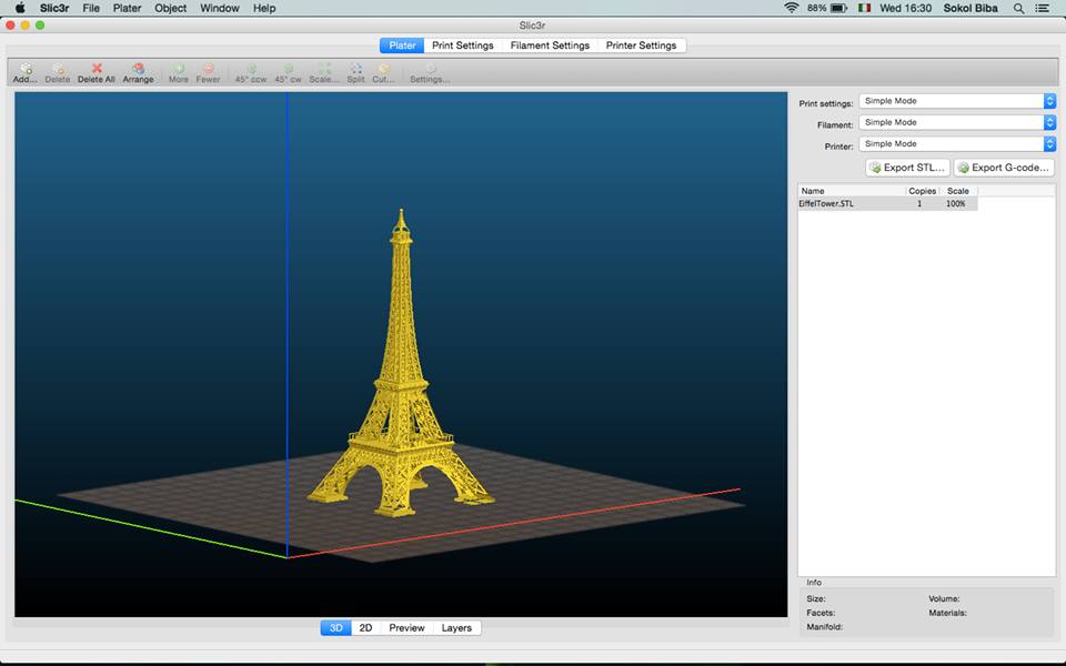
Now what is this G-code that the slicer software should produce? Nothing more than a list of instructions, readable by the 3D printer microcontroller, that tell the mechanical parts what to do, how to do it, and when to do it. The G-code for the above Eiffel tower model is 30820 lines of code long, and a small sample of it is given below (quite like Assembly, isn’t it?):
M107
M104 S200 ; set temperature
G28 ; home all axes
G1 Z5 F5000 ; lift nozzle
M109 S200 ; wait for temperature to be reached
G21 ; set units to millimeters
G90 ; use absolute coordinates
M82 ; use absolute distances for extrusion
G92 E0
G1 Z0.350 F7800.000
G1 E-2.00000 F2400.00000
; ...
; The rest of the code
This G-code is the input of the second software. After you generated the G-code of the model, you use a software to send this G-code to the microcontroller of the 3D printer. For this stage, we used Printrun. Printrun is an open-source G-code sender that consists of Printcore (dumb G-code sender), Pronsole (command line G-code sender), Pronterface (G-code sender with GUI), and a small collection of helpful scripts.
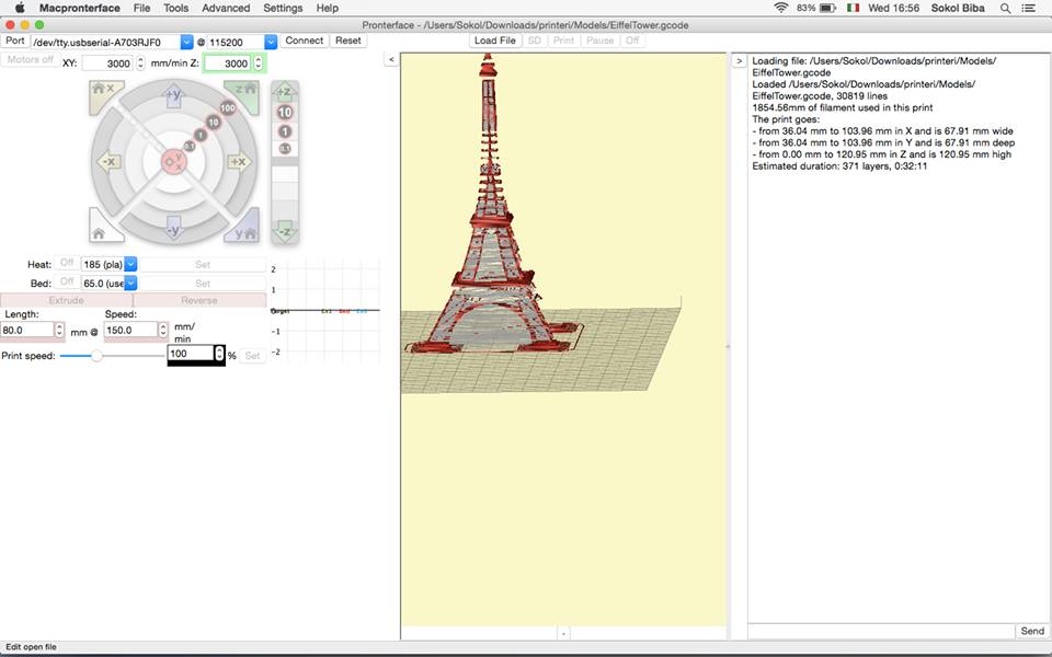
Pronterface is able to calculate the time of printing (32 minutes 11 seconds in the above example), but it also allows you to control the 3D printer manually. It allows you to control the steppers and the extuder, like:
- Moving in X, Y and Z direction a given distance in millimeters, with a given speed
- Printing a given amount of filament with a given speed (feed rate)
- Heating the print bed and the print head up to a given temperature
- A lot more.
This manual control of the printer is very helpful during the calibration process.
Of course there are other slicer and G-code sender software. Check out Repetier-Host, Skeinforge or others.
Calibration
Once you assemble the 3D printer and you wire the electronics, you are ready to use your printer, right? Don’t get disappointed, but you are not ready yet! What comes next is probably the most important stage of setting a 3D printer up and running: the calibration. The calibration is the collection of mechanical “tweaking” processes needed to get exact, quality prints. When you finish assembling and wiring the electronics, you can start printing objects, but the printout probably won’t have a good quality. It may not have the desired dimensions, it may not stick in the print bed during the printing process, etc.
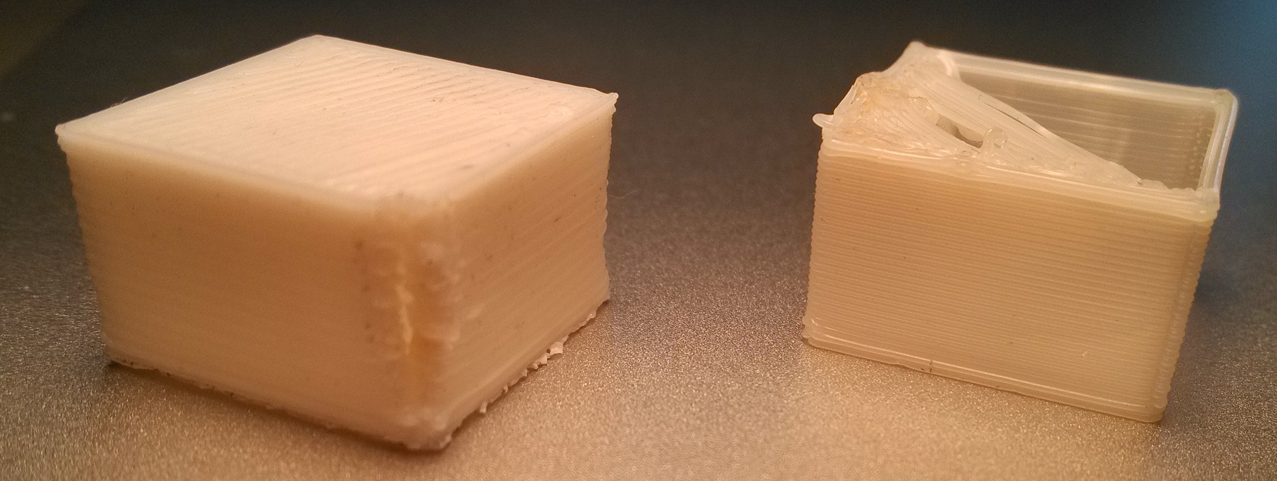
To start the calibration, you should firstly make sure that the print bed is leveled, everything is wired correctly and the printer is not shaking.
To perfectly level the print bed, you get a normal A4 paper and put it above the print bed. Then, you lower the nozzle of the printer until it almost touches the print bed, but doesn’t touch it. If you can easily move the paper while the nozzle is in 5 key positions (4 corners and the center) without ever touching the print bed, then you are ready to go. Otherwise, you would have to lower (or increase) one side of the print bed until the paper can be easily moved.
After that, you should obtain the firmware (see here a list of firmwares). There are different firmwares for different printers. We were using Megatronics v3, so the firmware for us was Marlin. In the firmware, you should set the type of the motherboard (i.e. the microcontroller) that you are using. For our firmware, we had to edit a file called Configuration.h where we would put all the configuration for our printer.
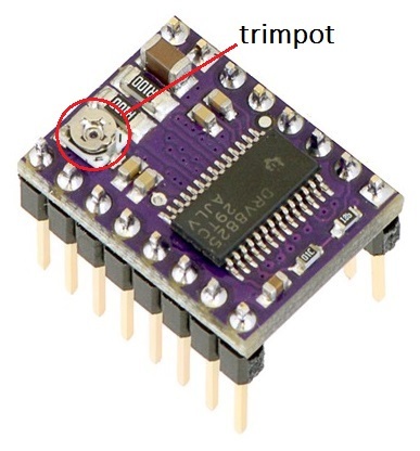
Watch the steppers! After picking your motherboard type, you should set the current that flows in each stepper. If it’s too high the steppers will start to make noise; if it’s too low they will vibrate but won’t move at all. At the motherboard you have a driver for each stepper, and each driver has a small trimpot (really small potentiometer) which you have to adjust in order to set the current at a desired value.
After making sure that the steppers are OK, you would normally go on with the thermistors: small temperature sensors that usually measure the temperature of the print bed and that of the print head. If you don’t explicitly set the configuration to match your thermistors, you won’t get real temperature data.
Endstops (A.K.A home buttons) are needed to be mounted in such way to tell the printer where to stop its movement on a given axis. There are two ways of telling the printer where to stop. One way is by mounting two endstops per each axis of movement. One of these endstops says “Start from here” while the other ones says “Go up to here”. Another way is by using “soft endstops”. This is done by telling the motherboard (by editing the configuration) where to stop the movement, by determining how far the axis can travel away from the physical endstop. These hard or soft endstops are all defined in the firmware.
During the printing process, the printout should stick in the print bed. If it does not stick since the beginning, the printout will move and the result will be a lot of material thrown away. Calibrating the print bed is done in two steps: leveling and making sure that the printout will stick. Normally, the print bed is made by a piece of glass, underneath which is a PCB connected to the motherboard.

The PCB is a big resistor which gets heated so the printout sticks in the glass above it. To make sure that the printout is going to stick in the print bed, most 3D printer owners add other materials on top of the glass. Some use ABS juice, some others (including us) use Kapton tape. Due to its stability in a big range of temperatures (up to 400°C), Kapton is used in spacecraft (including Apollo 11), as an electrical insulator in aircrafts, and to make the print bed more adhesive.
After adding Kapton tape to the print bed, we have to test its adhesiveness: we have to print. When you do this as a first print, you pay attention to three things (call them tests):
- The printout will stick
- The extruder nozzle is not printing more than it should
- The dimensions of the printed object are the desired
If the 1st test doesn’t pass, you should rethink of the print bed. You may have to increase its temperature, or think of another way to make it more adhesive.
If the 2nd and/or the 3rd test don’t pass, you have to change a line of code (the same for both problems) in the configuration file. If you check our configuration at line 403, you can see:
{% highlight c %} #define DEFAULT_AXIS_STEPS_PER_UNIT {80, 80, 731.43, 900} {% endhighlight %}
The first three values tell the steppers of the printer how much should they move in order to achieve the exact dimensions of the 3D model. The fourth value belongs to the stepper that controls the flow rate of the filament. You might be asking yourself “Why the magic values?”. Well, we calculated them using a simple formula known by every 7th grader, the rule of three. For the first three values we can write:
{% highlight c %} needed_value = (actual_value * distance) / actual_distance {% endhighlight %}
Initially, the first three values at that line of code above will have a default value (the actual_value of the formula). Using Pronterface (or any other G-code sender) you move one axis by a specified distance (the distance of the formula). Then, you measure the actual distance (the actual_distance of the formula). By using the formula above, you can calculate the value you should put there (the needed_value of the printer). On the same way, for the last value, you can use the formula:
{% highlight c %} needed_value = (actual_value * needed_consume) / actual_consume {% endhighlight %}
Now you “order” the printer to extrude an amount of filament (the needed_consume) and you measure how much it actually printed (the actual_consume).
After going through all these steps, you are ready of testing your 3D printer for the first time, by printing some real objects! I would suggest printing some simple and small objects firstly in order to check the calibration. These objects could be small squares, cubes, and other similar things you can find in Thingiverse. Later when the printer is well calibrated, you can go on with more complex prints.
